CTRL-ALT-ESCapement

I’ve been working on fabricating a wheeled mechanism for Reinventing the Wheel, and it’s been… an adventure. I’ve been trying to make an escapement mechanism, but I haven’t been able to find a proper name for this thing; the initial references that I’ve seen called it a controlled output escapement, but I can’t find any other mentions of this sort of machine. Either way, this is my reference inspiration An escapement uses a continuously rotating driver to actuate a follower at consistent intervals, in this case 90º at a time.
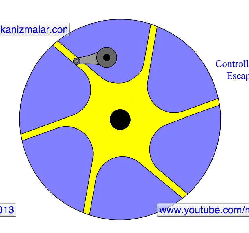
I started in Fusion 360 again. This was by far my most complicated model ever attempted and it was fairly successful, although I wouldn’t recommend my workflow to anyone just yet. I tried to take advantage of the 3D models that McMaster makes available for a lot of their components, which was helpful, but also exposed an obstacle in using Fusion. McMaster’s default is to offer their models as Solidworks files, and it turns out there’s good reason for that. Since Fusion obviously doesn’t support .SLDPRT files, I imported components as .STEP files, and they don’t function nearly as well. As models go they’re fine, but when I tried to manipulate them I ran into trouble. Specifically, sketching on faces, or creating new construction planes got extremely messy. The crossover clamps that I used, which I’ll address more in a moment, have angled faces, and Fusion really struggled to create a construction plane perpindicular to the internal cylinder instead of the face. Solidworks, on the other hand, can figure that out much more easily, which I’d hope, for $4000 a seat. Even with those struggles though, this was a huge accomplishment for me in regards to the CAD.

The actual fabrication didn’t go nearly as well. I made a prototype of the primary wheel from wood using the Roland mill, which came out wonderfully, but when I tried a final version in Delrin I got pretty terrible results, at least in terms of surface finish. I have a few theories about the source of the issues. I was cutting from a fairly long, but thin sheet of Delrin, which produced a lot of chatter sitting on the fourth axis (this is a scenario where it might be worth disconnecting the 4th axis and using the Roland as a regular 2.5D mill, but I’m not sure how easily that would disassemble). There’s also a strong likelihood that my end mill was slightly dull, since the adhesive in plywood can be surprisingly harsh to carbide, especially without perfectly optimized feeds and speeds. I get the sense it was at least somewhat dull, since the edge cuts on the wheel are much cleaner than the faces, which kinda gives me the sense that the upper parts of the flutes are in better shape. Also, I ran the Roland on its ABS presets, but I found out after the fact that it has settings for polyacetal, which translates as Delrin if you have a chemistry degree. Anyway, the end result is probably usable, but it’s going to require quite a bit of refinishing. I’d like to get it up on the lathe to face it. I tried run a second finishing pass on the Roland, but the software really objected to that idea, unfortunately.

Things didn’t get much better from there. I was somewhat overly optimistic in judging the tolerances for the parts I ordered, but even knowing that going in I wound up quite disappointed. The core challenge in building this assembly was going to be making an armature to hold the driver arm in perfect position above the follower, and I hit a number of problems in the process. The armature had to be able to sit rigidly over the follower wheel, and also hold the driver in position, sort of like a needle on a record player. It’s not a complex set up, but I struggled a bit in coming up with a design for it. Eventually I stumbled across the idea of using copper pipe and fittings, which seemed appropriately sturdy. Unfortunately, when I tried to source material I ran into issues finding the appropriate diameters. My driver arm sits on a quarter-inch axle, and I couldn’t find any pipes in that range, copper, plastic or otherwise; the smallest I could get to was a 1 inch outer diameter. What I did find though was unthreaded spacer stock, with an inner diameter of 1/4” and an outer diameter of 1/2”. I still couldn’t find any fitings that small, so I needed to scale up my diameter some how. I wound up selecting some large bushings, with a half-inch ID, and a 1 inch OD, which would be able to cap the copper pipe. The fit wasn’t amazing, but it all actually came together fairly well to that point.

That’s where things started to go wrong though. The crossover clamps that I bought wound up being a good bit wider than their listed tolerances, and had no real flexibility for further tensioning, so the pipes sat loose inside. I tried to remedy the situation by padding the outer diameter of the pipes with a thin later of high density foam, which initially seemed to work quite well, as you can see below.

Unfortunately, the crossovers wouldn’t sit flat, no matter what I did. At this point I’m not entirely sure how much of that is attributable to the poor fit, and how much was the clamps themselves. It seemed as though they weren’t particularly square either. I mounted the whole assembly to a wooden base using a steel flange (Sidebar: In retrospect, in the process of designing this, I forgot that steel and copper don’t play particularly nicely together. Not that material lifespan was really the point here, but it’s worth remembering). Fully assembled, it looked pretty good, but the results didn’t match. It spun freely enough, and with a little assistance the follower moved basically correctly, but holding the components weren’t staying in place, which caused everything to slip. It also seems as though the pin on the driver arm needs to be the full width of the channels on the follower wheel; if it lost contact at all then the motion was ruined, which I hadn’t realized on earlier attempts.
Controlled Output Escapement Assembly, Not Quite Working from Gabe Weintraub on Vimeo.
