Hot Wheels

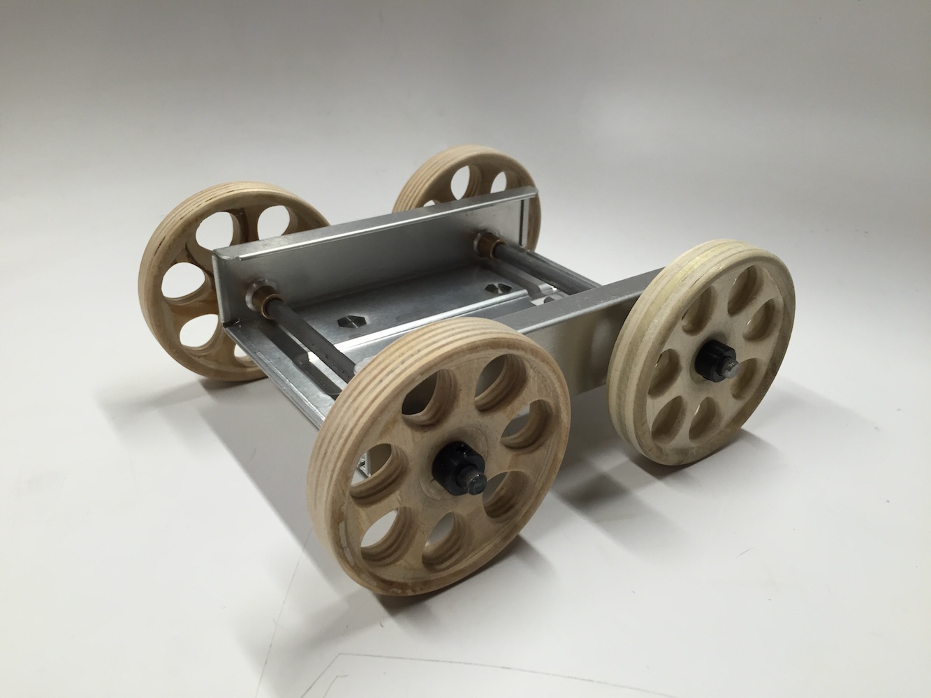
For the first couple weeks of Reinventing the Wheel I’ve worked on prototyping a set of four wheels and corresponding chassis. I fabricated my wheels from scratch, but used pre-fabbed components to build the chassis.
I’ve made it a goal this semester to improve with CAD, so I plan on modeling all of projects for this class. My weapon of choice will primarily be Fusion 360, since it largely duplicates SolidWorks’ approach to solids modeling and parametric design, but has also has the major advantage of being free. I’m also taking a SolidWorks (and ZBrush) workshop over at LaGuardia Studio, which so far has been helpful.
I did some research into hubcaps and rims for some inspiration, and decided on a general design, but I didn’t get into specifics until I started modeling. I decided to put a sloping inward taper on one of the faces, which wound up being quite a challenge, but I got basically what I wanted with what I assume was the least efficient methodology possible. The hub fits a quarter-inch shaft, and on the back face there’s an inset space for a bearing.
I manufactured the wheels using the Roland 4-axis CNC mill. The priority here was efficiency, so I simplified the cutting as much as possible. I wound up able to stick with larger tools, using a quarter-inch square end mill for roughing, and a quarter-inch ball nose mill for 99.9% of the finishing. Because the Roland CAM wizard is both limiting and unwieldy, I couldn’t cut the inset for the bearing to finished depth while roughing, and the ball nose couldn’t reach all of it, I wound up having to switch back to a square mill at the end for what came out to maybe 30 seconds of cutting. Tools changes on the Roland are pretty slow, so having to make an extra one was an obstacle, but since I would have had to change back to the square mill before cutting the next wheel anyway, it all worked out.
I used birch plywood stock since that was all I had laying around, but I didn’t decide on that before modeling. If I had I could potentially have factored the thickness of the laminate into my design, which would have given me some interesting surface patterns, but I didn’t end up with much contrast this way. I initially used ten layer ply, but I decided to try one with some five layer material. Honestly, there wasn’t much of a difference, although there may have been slightly more tear out with the five layer. I only encountered one significant void, and conveniently it was in an inauspicious area of the back face of the wheel.
I took off the majority of the tab material with a handsaw, but entirely evening the surface of the wheel required a power tool. As another issue I wish I had designed for, I didn’t have a proper mount for the lathe, so I had to improvise a bit. I used a bolt as a makeshift arbor, and then held that arbor in a Jacobs chuck, which I could fix to the headstock. It was only a taper mount though, so it was not an ideal set up, but fortunately I only needed to just touch the wheels with a gouge; any more and this likely wouldn’t have held up. The rest was sandpaper.
From there it was on to figuring out a chassis. Unfortunately that section was rushed, so I don’t have any in-process photos. In a stroke of luck I found an aluminum hard drive sled on the junk shelf. Not only was it sturdy, it also had two round indentations on each side, perfectly aranged for an axle. I’ve ordered another hard drive tray; this might be a recurring thing. I drilled out the holes, and the space wound up being a perfect fit for the bushings I planned to use. The wheels fit very snugly on the axle, but I added a shaft collar on either side to make sure they stayed fixed.
And the end verdict? It rolls!
